Drone Main System Configuration Diagram – Visualization of Innovation
RJ0400040_16
- Last Update 05/28/2025
- File Size 0.2MB
- # of Slides 2
- File Format PPTX
- Slide Ratio 16:9
- Color
Keywords
- #Content-Based Slides
- #Design-Based Slides
- #Product/Service Introduction
- #Technical Approach
- #Diagram
- #Differentiation Strategy for Products/Services
- #System Architecture Diagram
- #Cluster
- #Chain Diagram
- #16:9
- #drone system diagram PowerPoint
- #connection diagram slide template
- #control system architecture PPT
- #technical system visualization
- #drone technology presentation slide
About the Product
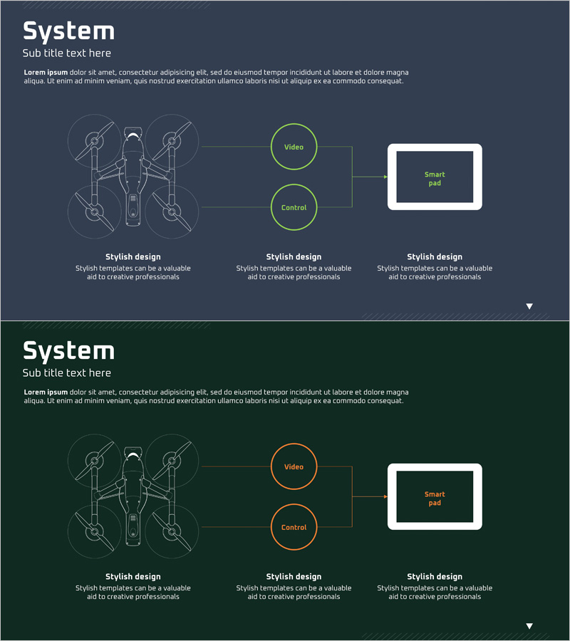
A connection diagram PowerPoint slide visualizing the core drone system with three key nodes: drone body, video module, and control interface. Set against a dark gray background with lime green accent colors, this slide clearly illustrates the control flow and data relationships essential for technical presentations and project documentation. The 2-slide set includes color variations (green and orange) to maintain visual consistency across your presentation deck. Ideal for drone technology, IoT systems, and control architecture discussions in engineering and product development contexts.
Usage Points
-
Main Usage
Effectively communicates the relationship between major drone system components—sensors, control units, and output devices—in a single visual. Designed to clarify technical architecture, system flow, and control logic for engineering and product audiences.
-
How to Use
Insert as a system overview slide in technical presentations, project proposals, or product introduction decks. Edit node labels directly, add arrows to show data flow, and leverage the two color variants to distinguish presentation sections or system states.
-
Recommended For
Drone and robotics engineers, product managers, technical sales teams, university instructors, and startup founders presenting to investors. Best suited for presentations targeting audiences with technical expertise who need clear system architecture visualization.
-
Slide Structure
Drone silhouette on the left connected to three circular nodes (Video, Control, Smart Pad) via connecting lines. Each node features a lime green or orange border for emphasis, with arrows indicating data flow direction. Both slides maintain identical layout with color variations for flexible use.
Related Products
-

Global Network Service Configuration Diagram – Product Differentiation Strategy
#Product/Service Introduction #Technical Approach #Diagram
-

Business Service Differentiation Strategy Diagram – Cluster Approach for Effective Marketing
#Product/Service Introduction #Marketing Plan and Strategy #Diagram
-

AI System Architecture Diagram – Key to Technical Operations
#Operational Plan #Technical Approach #Diagram
-

Hologram Wide PPT Connection Diagram – Service Composition
#Technical Approach #Diagram #Service Configuration Plan